How To...
Wire Analog Duct Detectors In Series Using Trouble Contacts
When wiring analog duct detectors to an SLC monitor module or directly to an FACP it is also required to incorporate the trouble contacts. Remember that in a supervised alarm circuit shorted circuits cause alarms and open circuits create panel troubles. One trick to remember is; all alarm contacts will have 2 wires or 1 wire and 1 resistor under each terminal. Trouble contacts will have 1 wire under each terminal.
Below is a typical Duct Detector Terminal Connection drawing. On this duct detector, you would use the 2A FACP Alarm Contacts and the 10A Trouble Contacts.
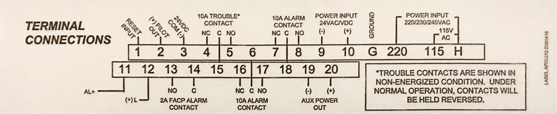
CAUTION: Look closely at the note regarding the trouble contacts.
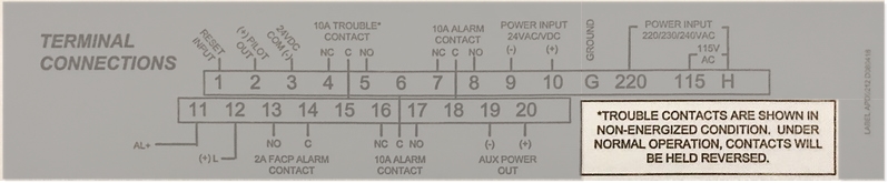
In this case, you would use the C(15) and NO(5) terminals to achieve a closed circuit during normal operation.
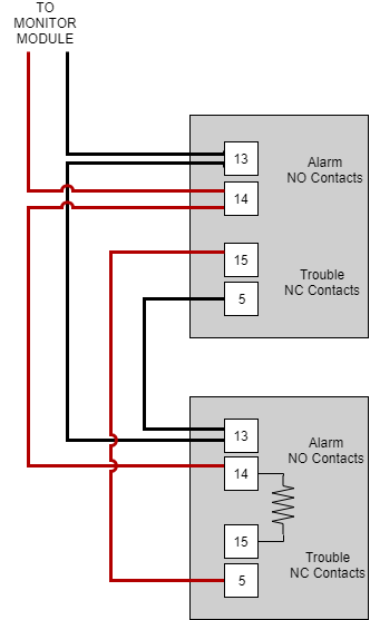
The drawing below shows the correct wiring for 2 duct detectors. The bottom image illustrates the wrong way to connect these detectors.

Notice that the alarm contact portion of the circuit does not pass through a tamper relay until the circuit has passed through all alarm terminals. If the first detector goes into trouble the 2nd detector must still be able to trip an alarm. The trouble relays are only used to open the circuit between the LAST alarm terminal and the EOL resistor.
To verify the circuit, start at the black wire from the monitor module, and follow the wired path. The alarm contacts are normally open so the path is to the terminal and back out again. When you get to the trouble terminals which are NC, you jump to the other trouble terminal. After going to the 2nd detectors alarm terminal the circuit passes through both trouble relays and the EOL resistor before heading back to the monitor module. A complete circuit with a supervision resistor.
Here is the same drawing with terminal numbers applied from the terminal connection drawing above.
A common mistake by many is to not run a 4 conductor between duct detectors. With only 2 conductors the circuit is usually wired as shown below. Notice that if the 1st duct detector trouble relay opens, the 2nd detector cannot initiate an alarm. It is critical that each detector remain fully functional in the event that another detector is in trouble.
INCORRECT WIRING METHOD
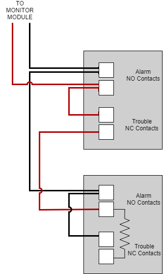
With incorrect wiring, the 2nd detector cannot function if the 1st trouble relay opens.