How To...
Wire and Programming AES 7707 and 7794A
Wiring Requirements:
Between the fire panel and the AES radio, install 3-18/2 firewire and 1-cat5/6. If the AES radio is powered from the fire panel, run the required wire at the same time. All wires need to be in conduit, flex or in wall. The radio must be within 20 wiring feet of the fire panel and in the same room.
Overview:
The AES 7707 radio with the 7794A Intellenet board for telephone interface provides two methods of fire panel condition between the radio and the fire panel.
The first method is through relays on the fire panel.
Most fire panels have three relays. A dedicated TROUBLE relay and two programmable relays which trigger on ALARM and SUPERVISION. Generally, the 1st programmable relay is set for a fire ALARM and the second relay for SUPERVISION.
The second method is through Plain Old Telephone Service (POTS) emulation provided by the 7794A Intellenet add-on board. The fire panel communicates to the AES as if the AES was a standard telephone line.
Connections:
The 7707 main board has multiple supervised input zones. For standard fire panel monitoring, wire 1-18/2 from left to right as follows,
ALARM – SUPERVISION – TROUBLE
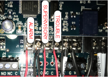
You will not enable the unused zones, but leaving the resistors in the enclosure or installed directly on the AES radio for future usage is a good idea.
Zones 1 and 2 shares a common ground as do zones 3 and 4 and so on.
Connect each wire to the corresponding fire panel relay using the COM and NO terminals for each relay. Install the supervision resistors provided by the AES radio in parallel on the same terminals.
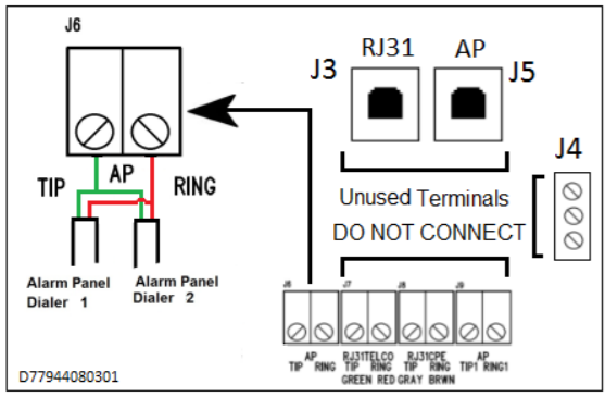
Using the cat5/6, connect pair 1 (w/blue-blue) to the Tip/Ring of the fire panel TELCO LINE 1 terminals. Now connect the pair 2 (w/orange-orange) to the Tip/Ring TELCO LINE 2 terminals.
White with blue stripe = Tip = Green
Blue with white stripe = Ring = Red
White with orange stripe = Tip = Black
Orange with white stripe = Ring = Yellow
At the AES Radio, connect both pairs to the AP Tip / Ring terminals on the 7794A. You must connect both pairs to the same terminal. There is only one POTS connection on the 7794A.
Make sure the wire insulation is not under the terminal screw.
Programming:
Important – When you save changes you must click Update on the top bar to actually update the radio.
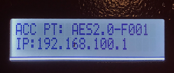
Programming is performed using a WIFI dongle inserted into a USB port on the upper right corner of the 7707 main board. Using a phone, tablet or laptop log onto the WIFI access point using the password “7707fire”. If a browser does not auto-launch, open a browser and access the 7707 using the IP address visible on the display.
Once on the 7707 web page, log in using admin/admin.
First, check the firmware version of the 7707 and verify it is the most recent available.
Once you have verified the firmware is up to date, you should scroll to the bottom of the System section and click on UPDATE. This will update the 7794A to the most current firmware.
In the Configuration section add the last four digits of the customer account number and enter the Encryption Key. (See system support for the correct the Encryption Key).
In the Accessories section, you need to activate the input zones for the ALARM – SUPERVISORY – TROUBLE relays. Turn on zones 1,2 and 3 and configure all three for FIRE. Set Restoral ON for all three zones. This will send a notification when the zone restores to normal.
Work with your system support or monitoring center to verify signals received.