Understanding Conventional 2-Wire Smoke Detector Wiring
** This article is for LOW VOLTAGE smoke detectors and NOT for 120VAC hardwired devices. **
Smoke detectors for security and fire alarm systems connect to a control panel in one of three manners.
1. 2-wire conventional
2. 4-wire conventional
3. Polling Loop (aka addressable, Used mostly in commercial applications)
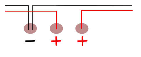
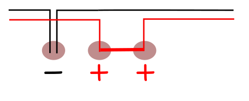
2-Wire conventional smoke circuits use a pair of wires for both power and signal functions. On 2-wire circuits, the detectors are wired in parallel along a single path with an EOL resistor at the end of the circuit. When any detector goes into alarm, the circuit is brought to a near short. The panel senses the near short and goes into alarm. Remember the end-of-line resistor is present to create a voltage drop across the terminals on the panel. A near-short bypasses the resistance and puts the detection circuit into an alarm state. The panel programming determines what action the panel takes in response. Go here for more on circuit states.

The image above shows a Smoke detector loop in an EOL state resulting in a Normal Condition. The detectors are powered through the loop with either 12VDC in a home security system or 24VDC used in most commercial applications. There are exceptions, so always check before you install or replace a smoke detector. Regardless of the system or the voltage that the system uses to power smoke detectors, the principle is the same.
Any detector which goes into alarm condition will “latch”. The term latch means the detector stays in alarm condition even when the smoke event is over. When latched, a detector will show a red light. This aids the user in locating which detector caused the alarm.

Detector latches and displays a red light. After the smoke clears the detector stays latched and the red light stays on.

When any smoke detector in the circuit activates, it disables any other detector from initiating an alarm. The panel can only indicate that that particular zone is in alarm.
To release the latch thereby resetting the system, power must be removed from the 2-wire circuit for a few seconds. When power is restored the smoke detectors return to normal operation. If the smoke circuit is reset before the smoke is cleared or if the detector is damaged from the event, the fire alarm will trip again.

During a Fire Reset, power is removed from the circuit for a few seconds.
Heat detectors can be installed on the same circuit as smoke detectors. They wire and function in essentially the same manner. The only difference is the type of conditions that trigger an alarm. While heat detectors can be added to a smoke detector circuit, it is often better to add the heat detectors to their own zone. This will provide more detailed location information to the monitoring station if dispatch is required. It is also important to remember that not all conventional heat detectors can be used more than once. These are called "non-resettable" and must be replaced after they activate. If included in a smoke detector circuit this may delay the re-activation of that circuit.
It is important to realize that the images above are shown in a schematic format and do not reflect the precise method of wiring a 2-wire smoke detector. The circuit must have the ability to open if a device is removed. The open circuit is the same as a cut wire. The panel goes into trouble. Below is a graphic of a commonly used base plate terminal. The smoke detector clips into the base. If the detector head is removed, the circuit needs to reflect the open circuit so the panel can go into a troubled state.
The + power leads are NEVER under the same terminal in a two-piece detector. Some detectors are wired directly to the sensor part and the base is only for securing to the ceiling or wall.
When a smoke detector is installed it bridges the gap between the two + terminals thereby completing the circuit for the rest of the detectors.
Notice the wires are NEVER twisted together. If a wire disconnects from the base it MUST open the circuit.