Fundamentals: Wire Terminations in a Fire Alarm System - NAC Circuits
Fundamentals in wiring are the same for all aspects of a fire alarm system. This article applies those fundamentals to Notification Appliance Circuits (NAC). Horn Strobes, Strobes, and Sounders all connect to the panel in the same manner. The fundamental function of a Fire Panels NAC circuit is to;
1) Notify the building occupants of danger and,
2) Monitor the electrical integrity of the circuit so the first function is not diminished.
To monitor the integrity of the circuit a resistor is installed at the end of the circuit. This resistor creates a voltage drop which is measured by the panel. If a device is removed, the circuit is broken and the Fire Alarm Panel creates a trouble condition. If a wire is cut or comes loose from a terminal, the circuit is broken and a trouble condition is created. All the wiring fundamentals presented here are required to assure the NAC circuit operates properly and alerts the user in the event of a wiring fault.
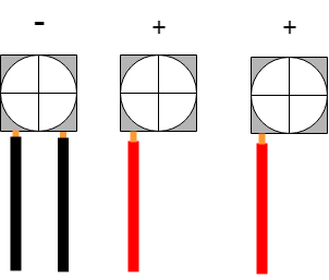
The image below illustrates the correct wire connection on a NAC device. When the device is installed it will complete the connection between the two + connections. When the device is removed, the circuit is broken.
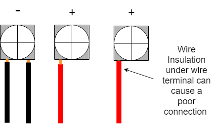
When the insulation of the wire is placed under the terminal wire clamp, it can lead to a very poor or no connection. Locating these wiring faults can be VERY VERY difficult. Always make sure you can see a little copper.
You should always be able to see a slight amount of copper.
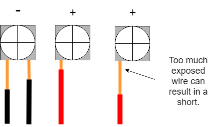
This is not correct. The bare wire should not be able to reach ANY other wire or terminal.
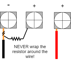
The image below shows the last NAC device and the End Of Line Resistor, commonly referred to as EOL. Just like the other NAC devices, when installed, the device will complete the circuit across the two + terminals.
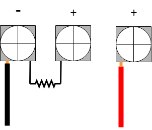
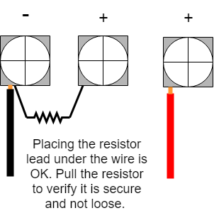
It is not always easy to secure the resistor lead under the same terminal as the larger diameter wire. It is generally incorrect to install two different guage wires under the same terminal. To help keep the resistor secure, it is acceptable to place the resistor lead under the larger wire. Fold the end of the resistor lead over (about 1/4 inch) and slide the resistor under the larger copper wire. Tighten the terminal and give the resistor a tug to verify it is secure. IT IS CRITICAL the resistor is firmly secure.
While it is tempting to wrap the resistor lead around the wire, DO NOT. Remember that the fire alarm panel must be able to monitor that every device is connected to the circuit. If you wrap the resistor around the wire and that wire becomes disconnected from the terminal, the circuit is not broken.