RJ-11 and RJ-45 Pinouts for Data and Telephone
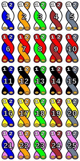
RJ-45 Pinout
While the T-568B pinout is more common, ALWAYS verify when starting a new project. It is not uncommon to see the A standard required. The standard required, usually applies to laying down and punching patch panels and wall plate modules or keystones. As long as both ends of a patch cable are the same the cable will work.
A cross-over cable uses T-568A on one end and T-568B on the other
Telephone Wiring - Pairing and Connector Pin-Outs
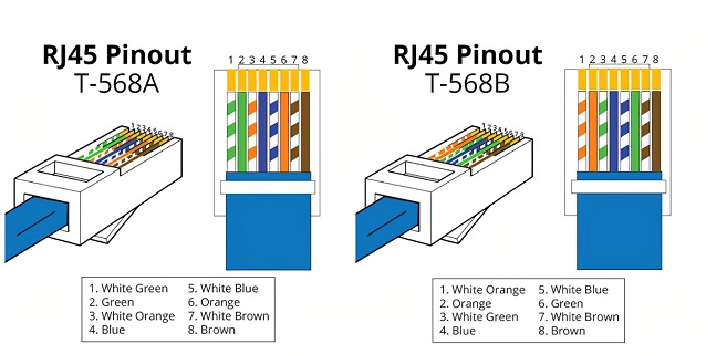
When discussing telephone wiring, it is common to refer to wires as pairs and not colors. In the image above, you can see the labels T1, R1, T2, and R2. The T and R refer to the terms Tip and Ring. Don't worry about the terms Tip and Ring.
It is important to remember that the base color wire is always TIP and the solid base color is always RING.
It's also important to remember that Pair 1 is always the Blue pair, pair 2 is always the Orange pair, Pair 3 is always the green pair, and brown is always the 4th pair.
Pair 1 = Blue Pair
Pair 2 = Orange Pair
Pair 3 = Green Pair
Pair 4 = Brown Pair
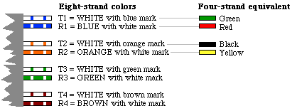
Telephone Plug Pinout
RJ-11 is a 4 Conductor (4C), 4 Position (4P) plug, using Pair 1 and 2 from the image below.
RJ-12 is a 4 or 6 Conductor, 6 Position (6P) plug using Pair 1,2, and 3
RJ-45 is an 8C8P plug as seen in the image at the top of this page.
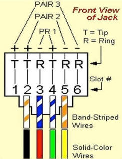
25 Pair
As you move up in pairs, the base color changes. Pairs 6 - 10 use a red base, 11 - 15 use black, and so on as seen in the image below. When you reach 50 pairs, the color scheme starts over but every 25 pairs, known as a binder group, is wrapped in a mylar color-coded ribbon. The first binder group is wrapped in a white/blue ribbon, the second binder group is wrapped in a white/orange ribbon. This process goes out to 600 pairs, where it starts all over.